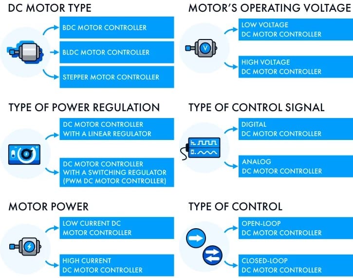
In our previous tutorial we already discuss about Working principle of electrical motor– its types, applications and all the parameters in this tutorial we will discuss all about DC motor controller-its working principle, types application overall, how these dc motor controller works so let us begin
Definition of DC motor controller
A DC motor controller is a device that regulates the speed, direction and other parameters of a direct (DC) motor. It commonly employed techniques such as pulse width modulation (PWM) for speed control and H-bridge configuration for direction control.
Some controllers include current sensing, voltage regulation and feedback mechanisms (close loop & open loop) also some are use hall effect sensors for previous control.
Block diagram of DC motor controller

Key components
As the diagram shown various components of motor controller
Let us discuss one by one
- Controller:
In this step the system checks how well the motor is performing compared to the desired speed or position. If there is a difference (an error) occur then the controller figures out the right adjustments needs and sends those instructions to the motor driver for correction.
- Motor Driver:
This stage boosts the control signal which come from the controller and directs it to the motor. The motor driver adjusts the average voltage to the motor using a method called pulse-width-modulation (PWM).
If the controller gives some error signal, only then this driver adjusted the motor applied voltage.
- DC motor:
The motor converts electrical energy into mechanical energy, such parameters like speed, torque are depending on applied voltage to the motor.
- Speed sensor:
A speed sensor measures the velocity of the motor and provides corresponding feedback to the system.
- Feedback speed:
In this block the system keeps an eye on the real speed or position of the motor and share this data with the controller.
Again, the controller takes the feedback of motor speed and measure it with desired speed if there is any error signal occur then provide it to driver, this process is continuous in real time.
Working principle of DC motor controller
Now understand the core concept of controller-
A DC motor controller handles the power going to the motor to control its speed and direction. It’s like a smart system that checks how the motor is doing and makes adjustments to keep it run smoothly.
DC motor controllers typically includes components such as transistors MOSFETs (Metal-Oxide-Field-Effect-Transistor) in some rarely cases relays can be uses, so basically these devices perform switching to modulate the current flowing through the motor.
By adjusting the voltage or current supplied to the motor the controller can regulated the motor’s speed, torque and directions of motor.
Types of DC motor controllers

Direction controller: H bridge
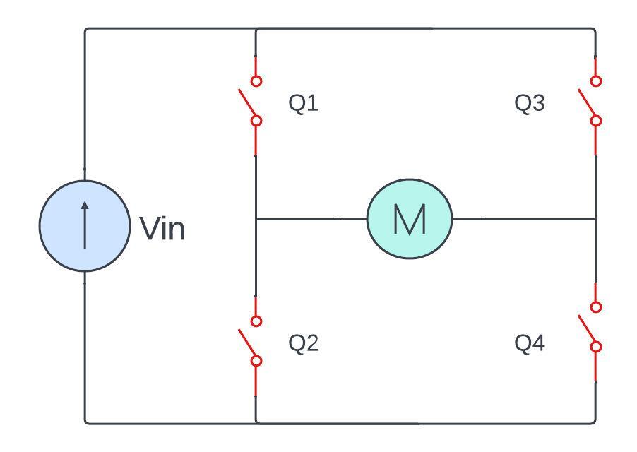
H- Bridge controller is a specific electronic circuit configuration has a widely used in directional controller for DC motors. It has bidirectional control capacity that mean they can rotate motors in both forward as well as reverse bias direction.
The name is H bridge because it has four switches (MOSFET) in H shape manner. Each switch controls the connection between the motor terminals and power supply. The arrangement of switches determines the directions of the current flow through the motor.
Components of an H-Bridge

- Switches (Transistors or MOSFETs)
there are four switches in this H-bridge configuration, they can represent as Q1, Q2, Q3, Q4 respectively. These switches either transistor or Mosfet because we required more fast switching so they are suitable.
2. DC motor
The DC motors is connected to the H-bridge and the direction of rotation is controlled by changing the polarity of the voltage applied to the motor terminals.
3. Supply voltage
A power supply provides voltage that drives the motor. the H-bridge allows the direction of the voltage to be controlled.
Now move one step ahead and let’s discuss the Operation of H-Bridge controller
In this post we will discuss only basics, in upcoming tutorials we discuss H-Bridge in brief manner.
Operation of H-Bridge controller

- Forward direction:
To make the motor rotate in the forward direction Transistor / MOSFET Q1 and Q4 are closed (conducting) at a same time Transistor Q2 and Q3 are open (non-conducting).
So hence the circuit is completed then current is allow to flow from the positive terminal of the power supply through Q1 to motor then Q4 and back to the negative terminal.
- Reverse direction:
For reverse direction operation transistor Q2 and Q3 should closed (conducting) while Q1 and Q4 are in open position (open switch).
This opposite in current flow through motor causing it rotate in the reverse direction.
| Q1 | Q2 | Q3 | Q4 | Result |
| 1 | 0 | 0 | 1 | Motor moves forward |
| 0 | 1 | 1 | 0 | Motor moves Reverse |
| 0 | 0 | 0 | 0 | Motor coasts (Free Run) |
| 1 | 0 | 0 | 0 | |
| 0 | 1 | 0 | 0 | |
| 0 | 0 | 1 | 0 | |
| 0 | 0 | 0 | 1 | |
| 1 | 1 | X | X | Short circuit |
| X | X | 1 | 1 | |
| 1 | 0 | 1 | 0 | Brakes |
| 0 | 1 | 0 | 1 |
- Breaking (Dynamic Breaking):
A breaking in motors can be achieved by shorting the motor terminals together. This is done by closing both the top-left (Q1) and top-right (Q3) switches simultaneously. Hence creating a short circuit across the motor terminals. The motor acts as a generator and the energy is dissipated as heat.
- Coast (freewheeling):
In the off state, where all switches are open (no current flow) therefore the motor is allowed to coast. The momentum of the rotating motor keeps it moving until external forces slow it down.
Speed controller: pulse width modulation (PWM)
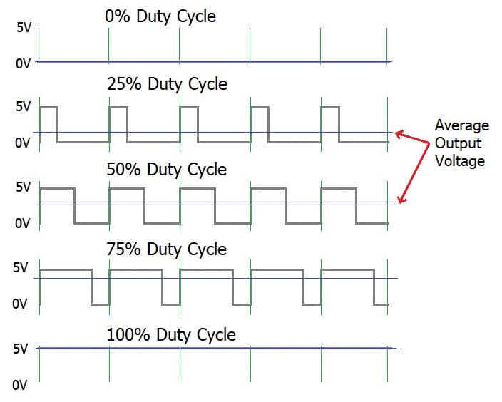
Instead of adjusting the voltage directly pulse width modulation (PWM) is like a speed regulator for DC motors. PWM controls the average power delivered to the motor by rapidly tuning it on and off.

By adjusting the duty cycle (percentage of time the power is on) we can precisely set the motor speed that making it versatile for various applications.
PWM speed control is widely used in robotics, fans and other devices where precise control over speed is essential.
Armature controller: variable resistance
In DC motor controller there is another method which is armature controller. By changing the resistance in the motor circuit. In this method a variable resistor is connected in series with the armature winding of the motor.
As we know the resistance is increases the voltage drop also increases therefore the voltage available to the armature will reduced.

In this way by reducing the flow of current flowing through the armature we can control the speed of motor. To achieve that we can use Rheostat, potentiometer or solid-state devices these all are variable resistance devices.
Advantages is that it is simple and inexpensive, easy to implant and provides good speed control.
There are some disadvantages like as- wastage of energy in form of heat, it can reduce only speed of motor but can not increase.
Factor to consider when selecting a DC motor controller
When we are going to select a DC motor controller there are several factors that has need to be consider for ensure proper functionality and efficiency. Here are some key factors to keep in mind:
1. Voltage and current rating: ensure that the controller can handle the voltage and current requirements of the DC motor.
Motor Types: different DC motors (brushed, brushless) may require specific type of controller.
2. Control method: we must decide which control method required for application open loop or closed loop.
3. Speed / torque: estimate the required speed and torque and ensure that either this controller provides or not according that we an select a best controller.
4. Efficiency: efficiency is the key factor of the selecting a DC motor controller. Choose a controller with high efficiency to minimize energy losses and heat generation, especially for battery-powered applications.
5. Security / protection features: must check the protection features such as over-current protection, over-voltage protection and thermal protection to safeguard both motors as well as the controller.
Such others factor like as-
6. Cost
7. Easiness of integration
8. Programming and configuration
9. Communication protocols
As we see above discussion about- Working of DC motor controller Here one question come in mind so what is exactly open and close loop system, so let’s make it clear.
Open loop and close loop control system

Open-loop control system:
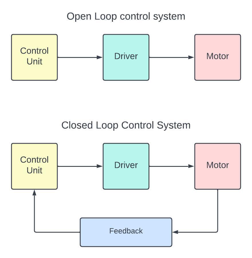
An open-loop control system will not give any kind of feedback mechanism so it will not adjust or change any output based on the real time system performance.
This system is totally based on the predefined algorithms. There is no need to change any parameters. An open loop-control system gives simple design but have some disadvantage like- lack of accuracy and reliability also give less efficiency.
Close-loop control system:
On the other hand, closed loop control system has a feedback system for modification in real time operation hence the system output maintains the desired output.
This system continuously monitors the output and compared it with the reference input to make necessary adjustments.
A feedback mechanism loop helps to increase efficiency and reduce the errors and disturbances that makes it more suitable and more accurate and stable.
Close loop systems are generally more complex than open loop system due to the feedback mechanism.
Applications of motor controller
Industrial Automation
To achieve perfect speed, torque and direction in industrial application motors controllers are plays major role.
Electrical vehicles (EVs)
In EVs motor controller manage power distribution to electric motors, also plays a crucial role in achieving optimal performance, energy efficiency and better control over speed and acceleration.
Robotics
Robotics are primarily work on motor controller to run precision momentum for arms and other motorized components. Lots of robotics applications required accuracy and repeatability for that motor controller is a perfect choice.
Advantages of motor controller
For controlling speed and torque of motor
Give accuracy and precision control
Minimize wear and tear that lowering the maintenance
Disadvantages of motor controller
There are certain disadvantages also as below-
It increases overall cost and complexity of the system.
requirements high skills operator.
frequently Asked Questions
Q. What are brushless dc motor controllers?
Ans: A brushless DC motor controller is designed for control the specific speed, direction and torque of the brushless DC motors.
Q. what is Motor driver?
Ans: Motor drivers has basic functions like driver power and primarily amplifies the signals to provide enough power. It is a less complex consisting transistors or MOSFETs that are arranged in H-bridge configuration.
Q. what are the unipolar and bipolar drive?
Ans: in unipolar drive a stepper motor coils are powered using one type of electrical flow at a time hence simplified the control system. in contrast bipolar drive uses both types for better efficiency but demands more complex control electronics.
Summary
Here is the short summery – a DC motor controller manages a DC motor’s speed, direction and power that are uses in electronic control methods to adjust the current flow for accurate motor performance.
Key features include sensors for feedback system, PWM for speed control. It has crucial role in robotics, automation and electric vehicles.
That all about DC motor controller. You can check more tutorials on Electric motor
Also Read:

nice article
helpful content
Sir you are great and nice content