A full wave and half wave rectifier is an electronic circuit designed to convert alternating current (AC) into direct current (DC) while minimizing the pulsating or fluctuating nature of the output voltage.
The DC output is generated by a full-wave rectifier has a significance ripple that causes voltage fluctuations over the time that is make lack of stability in circuit applications to address this issue filters are employed at output.
We already cover a full tutorial on Working of full wave bridge rectifier you can check it for more information.
In this tutorial we will cover Working of a full wave and half wave rectifier with a filter its importance, diagram, applications and many more.
Definition of full wave rectifier with filter
A full-wave rectifier is an electronic circuit designed to convert alternative current to direct current by utilizing both halves of AC waveform. In half-wave rectifier it uses only one half of the AC cycle.
Working principle of full wave rectifier with filter
A filter is typically employed to give smooth output from pulsating DC output of the rectifier. Commonly capacitors are employed for filtering. For improving averaging of DC output this filtering technique are use.
The filters reduced the Ripple voltage also produce more stable and continuous DC voltage. This combination of full-wave rectification and filtering improves the efficiency and reliability of the DC power supply.
Half Wave Rectifier with Capacitor Filter
A half-wave rectifier is an electronic circuit that converts only one half of an alternating current (AC) into direct current (DC) by using a simple single diode. The efficiency is less in half-wave rectifier.

as we see in the figure first component is Diode this diode allows the positive half-cycle of the AC input signal to pass through the circuit and blocking the Negative half-cycle.
So as result we get only positive half portion of the AC waveform to output.
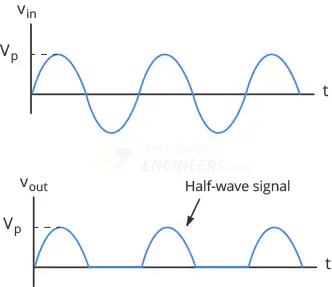
After the half-wave rectification, the output is still pulsating DC signal with have some significance ripple so to smoothen this pulsating DC we have to connect a Capacitor in parallel to the load (Resistance).
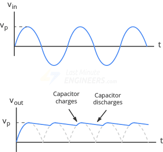
Case Ⅰ: During the positive half-cycle of the AC input the capacitor is charged to its peak value of the rectified voltage
Case Ⅱ: During the negative half-cycle of the AC input the diode is blocked the current and capacitor is discharges into the load.
The charging and discharging process of the capacitor will helps to reduce the ripples in the output voltages.
Voltage output
A voltage level across the capacitor tends to hold the voltage at a more constant level during the time between the AC cycle that gives smoothing out the pulsating DC.
The output voltage is the sum of the DC components and the ripple voltage.
Ripple Voltage
Capacitor filter reduces the ripple in the output voltages but some ripple may still be present due to the finite capacitance of the capacitance and the load resistance
The formula of ripple voltage (Vr) is gives as:
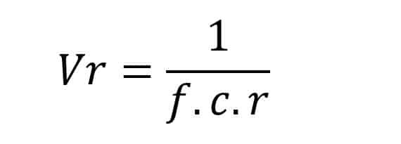
Were,
f = frequency of the AC input
C = capacitance of the capacitor
r = load resistance
Full Wave Rectifier with Capacitor Filter
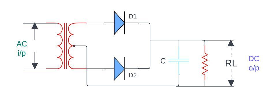
In a full-wave rectifier both positive and negative halves of the AC input waveform are used. This type of filter with capacitor gives more efficiency for converting AC to DC compared to a half-wave rectifier because it utilizes both halves of AC waveform that resulting in a smoother DC output with reduced ripple.
For more information we will do analysis of Full Wave Bridge Rectifier with Capacitor Filter
Full Wave Bridge Rectifier with Capacitor Filter
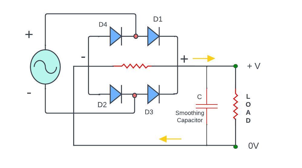
This is typically Bridge rectifier configuration which utilizes four arranged in a bridge-like pattern. diodes are ensured that the current flows in the same direction through the load during both half (positive and negative) AC cycle resulting in a more continuous DC output.
Like the half-wave rectifier with a capacitor filter here also capacitor is connected in parallel to the load (Resistor).
Case Ⅰ: during the positive half-cycle of the AC input one pair of diodes (D1 & D2) are conducts that allowing the capacitor to charge to peak value of the rectified voltage.
Case Ⅱ: during the negative half-cycle the other one diode pair (D3 & D4) are conducts that allowing the capacitor to discharge into the load.
Output voltage:
The voltage across the capacitor helps to smooth out of the pulsating DC obtained from the full-wave rectifier.
Here is the output voltage is the sum of the DC components and reduced ripple voltage due to the capacitor filter.
Ripple Voltage:
The ripple voltage in full-wave rectifier with a capacitor is generally lower than half-wave rectifier with a similar filter.
What is the basic purpose of filter in rectification?
Basically, the noise filter serves the purpose of smoothing the pulsating or fluctuation direct current output. Rectification is the process of converting AC into DC current. Filtering is employed to reduce or eliminate these ripples and gives more stable and constant DC output.
This is very crucial process for many electronic devices and systems that required and smooth source of power.
So here is one question come What is the necessity of a filter in a rectifier circuit?
Let’s see one by one –
Smoothing Output:
the primary purpose of the filter is to smooth the pulsating DC output generated by the rectifier.
Reducing of Ripple Voltage:
filters are often in form of capacitors and inductors these are used to reduce the ripple voltage in rectified output.
Improvement DC wave quality:
by smoothing out the output the filter improves the quality of the DC signal this is very crucial applications where a clean and stable DC voltage is necessary.
Minimizing the Harmonics:
the purpose of filter in rectifier because sometime rectifier introduces harmonics into the electrical systems due to the non-liner nature of their operations.
Enhanced efficiency:
a filtered rectifier output is more efficient for power electronic devices.
Noise reduction:
filters also help in reducing electrical noise that may be present in the rectified output. This is particularly more important is sensitive electronic circuits where excessive noise can interface with proper operation.
Advantages and limitations of RC filters in full wave rectifier
Lets see advantages of RC filter in Full wave rectifier
- Simple design
- Low cost
- Easy integration
- Low power consumption
- Phase shift control
- Smooth frequency response
The limitations of RC filter in full wave rectifier as below
- Limited roll-off rates
- Frequency dependence on components
- Sensitivity to tolerances
- Inability to provide s electivity
- Limited applications range
- Loading effects
Further Explore:
How does a full wave bridge rectifier work
Diode Definition, Types of Diodes, V-I Characteristics & Application
Zener Diode – Working, Characteristics and applications
Schottky Diode: Definition, Symbol, Working Principle
Frequency Asked Questions
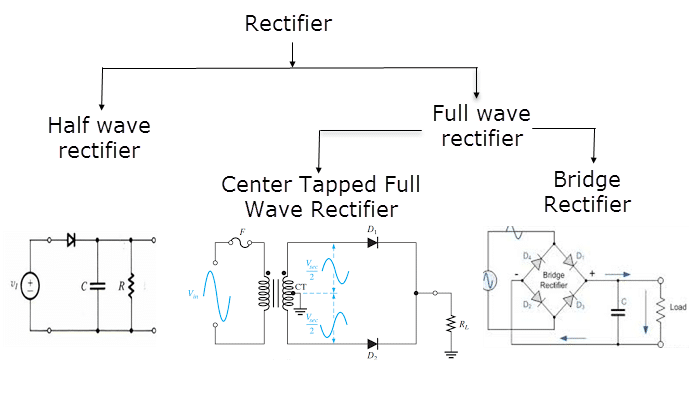
Q. What are the two types of full wave rectifier?
Ans: there are two types of full wave rectifier
- Half wave rectifier
- Full wave rectifier
Q. What are the 4 types of filters?
Ans: there are primary 4 types of filters in electronic that are – here is the simplest explanations
- Low pass filter (LPF): the LPF permits low-frequency signals and rejects the high frequencies.
- High- pass Filter (HPF): permits high-frequency signal and blocks the low frequencies
- Band–Pass Filter (BPF): the band pass filter allows a specific frequency range and reject the other frequencies.
- Band–Stop Filter (BSF) or Notch Filter: this is opposite to the BPF this Attenuates a specific frequency range and allows other to pass through.
Q. What is a rectifier example?
Ans: Importance of rectifiers in electronic circuits such as
- Power supplied for electronic devices
- Battery charger
- Audio amplification in amplifier
- Solar power system in solar invertors
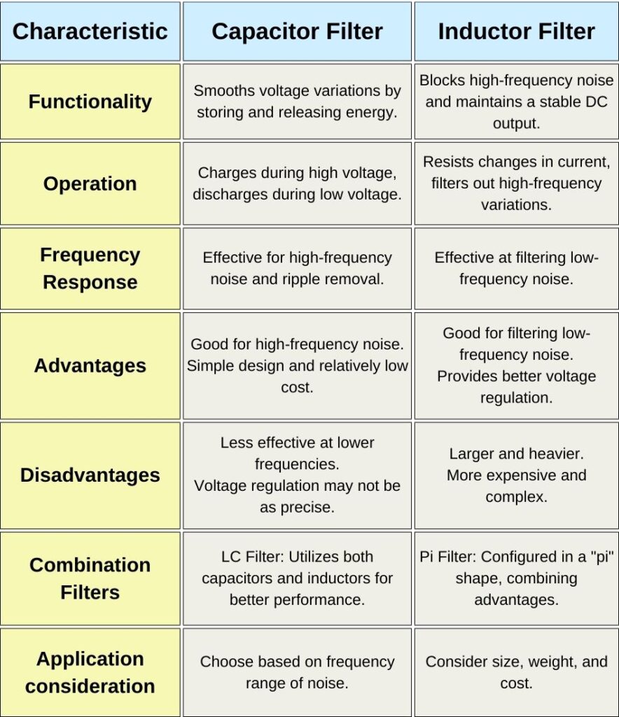
Q. Comparison between capacitor and inductor filters

good quality content and easy to understand. content structure and diagram are good in quality.