Definition of Class B amplifier:
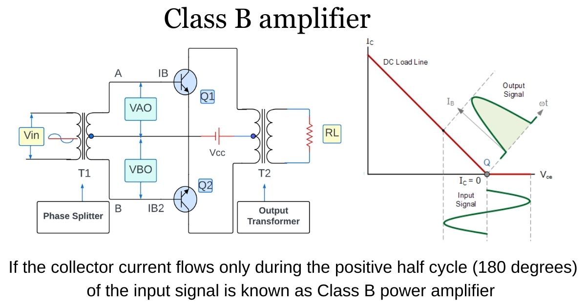
A class B power amplifier is When the collector current flows only during the positive half cycle (180 degrees) of the input signal. means for the entire input cycle, we are getting only Half output.
A class B power amplifier amplifies input signals using two transistors (NPN or PNP), each handling the positive and negative halves of the signal, resulting in higher efficiency due to reduced power dissipation. This makes it suitable for power-sensitive applications, to get the entire output using two transistors, which are known as push-pull transistor.
What is a Class B Amplifier?
To give more efficiency than the Class A amplifier by reducing the wasted power in the form of heat, it is possible to design an amplifier circuit with the help of two transistor this term is known as a Class B Amplifier, also called as a push-pull amplifier configuration.
working principle of class B amplifier:
classification of Amplifiers based on its size, processing speed, I/O configurations, load capacity like class A amplifier, class B amplifier, class C amplifier, class D, and class AB.
Class B amplifiers are much more efficient than Class A amplifier as we already have posted an article in class A amplifier in previous article “Fundamentals of The Class A amplifier-power amplifier”

Working principle of Class B Push-pull Amplifier:
As we know in class B push-pull amplifier the transistor biasing and input signal will flow in such a way that the output current is available only for the half input that means for the entire input cycle, we are getting only Half output.
To get the entire output simply use two transistors, which are known as push-pull transistors, in which one transistor is pushed into conduction and the other is pulled out of conduction.
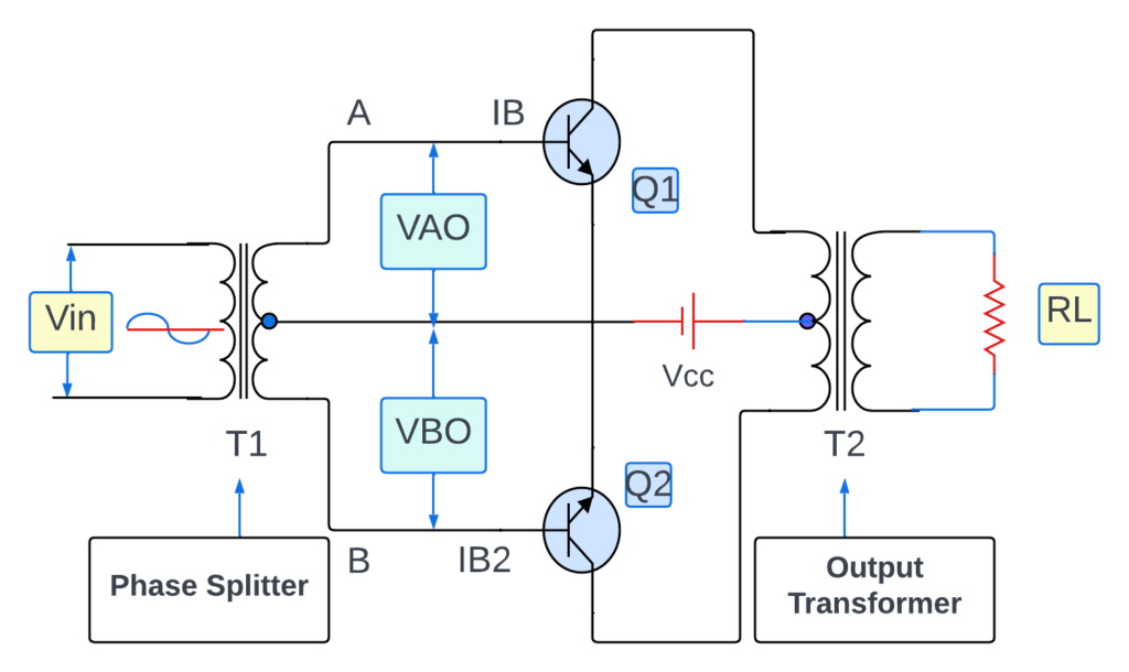
In the diagram of class B push-pull amplifier there are two transistors, namely transistor Q1 and Q2. the input is applied through Transformer T1, which is also known as phase splitter. phase splitter is a device that split the input signal into two halves, here is VAO and VBO, VOA is exactly 180 degrees faze shift with VBO.
apply VCC to both the transistor the output Transformer T2 which is directly connect to the load register RL. when there is no input signal both transistors Q1 and Q2 are at cutoff Biased
when applying AC input signal to the amplifier circuit, during the half positive cycle of input signal the voltage VAO is positive and voltage VBO is negative so change the positive voltage is applied to the base emitted junction of Q1 transistor.
This Q1 transistor will be in forward bias and Q2 remain reverse bias, Current IB will flow through the transistor Q1 and current IB2 will not flow through the transistor Q2.
As the IB flow through transistor (Q1) these current is applied to primary winding of Transformer T2 voltage is couple to the secondary winding and we get the positive output across load register which is amplified version of the input signal now during the negative half cycle VAO voltage become negative and VBO voltage become positive.
Transistor Q1 will Act as an open switch and Q2 act as a closed switch due to the positive voltage applied to transistor Q2 base emitter terminal Q2 will be on and Q1 will be remaining off so in this time current IB2 will flow Through the transistor Q2 And the current will flow through the transistor to load register and we will get output voltage so we can say that during the positive half cycle transistor Q1 is on and Q2 is off and we will get the positive output also for during the negative half cycle transistor Q2 is on and transistor Q1 will be off And we will get the negative output.
Hence because of two transistors during positive half cycle one transistor is push into conduction and other is pulled out of the conduction similarly during the negative half cycle one transistor is push into conduction and other is pulled out of the conduction Due to the Action we will get the maximum output for the entire cycle of the input signal this is the advantage of class B power amplifier.
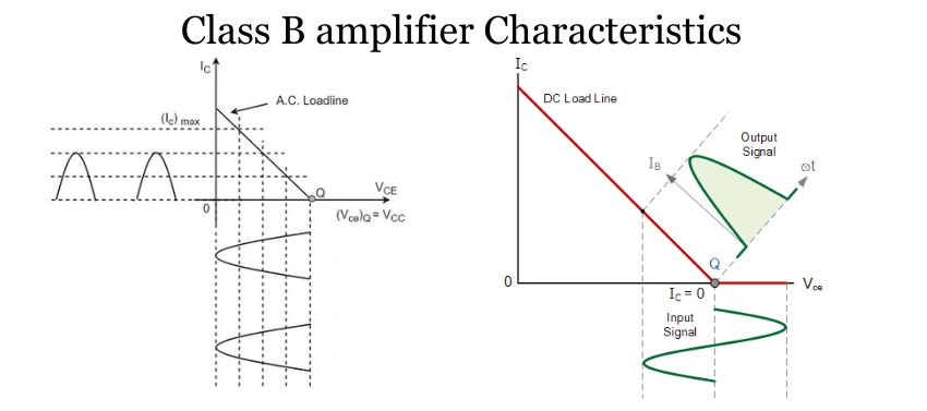
Class B power amplifier Output Characteristics:

- Class B power amplifiers operate with two transistors.
- Each transistor amplifies either the positive or negative half of the input signal.
- High efficiency due to reduced power dissipation.
- Suitable for high-power applications, such as audio and RF amplification.
- Can experience crossover distortion at the transition between transistors.
- Class AB amplifiers used to mitigate crossover distortion.
key formulas for Class B amplifiers:
- Efficiency (η):
Class B amplifiers are highly efficient and can be calculated using the formula:
% Efficiency = Po(ac)/Pi(dc) x 100 %
= [pi/4] x [VL(p)/VCC] x 100 %
[Maximum efficiency = [pi/4] x 100% = 78.5%]
2. Power Delivered to the Load (Pout):
The output power delivered to the load can be calculated using Ohm’s law:
Pout = (Vout^2) / (2 × RL)
Where:
Pout is the output power.
Vout is the peak output voltage.
RL is the load resistance.
3. Maximum Theoretical Efficiency (Ideal Class B):
Maximum efficiency = 78.5%
4. Crossover Distortion Reduction (with bias voltage):
Apply a small bias voltage to always keep the transistors slightly conductive.
5. Total Harmonic Distortion (THD):
THD is a measure of signal quality and can be relatively low with proper design, biasing, and transistor matching in Class B amplifiers.
Transformerless Output Stage:

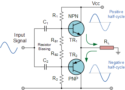
A transformer less output stage in a Class B amplifier is a design that connects the amplifier directly to the load, such as a speaker, without the use of an output transformer. This design offers advantages in simplicity, cost-effectiveness, and efficiency.
However, it requires careful consideration of impedance matching and lacks galvanic isolation between the amplifier and the load. Transformerless output stages are commonly used in modern solid-state audio amplifiers where compact size and efficiency are important factors.
Applications of Class B power amplifiers:
- RF Transmitters: Commonly employed in radio frequency (RF) transmitters for efficient signal amplification.
- Audio Amplification: Used in high-power audio amplifiers for public address systems, home theatres, and music amplification.
- Telecommunications: Used in telecommunications equipment, such as high-power transmitters and signal boosters.
- Power Amplification: In power electronics, Class B amplifiers are used to amplify and drive power signals for various applications.
- Instrumentation: Class B amplifiers are found in measurement instruments and signal generators.
- Signal Modulation: Used in amplitude modulation (AM) transmitters and other modulation applications.
- Public Address Systems: Amplifying audio signals for large-scale public address systems in arenas, stadiums, and public venues.
- High-Efficiency Systems: Where power efficiency and heat dissipation are critical, such as in battery-operated devices or high-power systems.
Advantage of class B power amplifier:
- efficiency of class B amplifier is 78.5%
- it eliminates even harmonic in AC output
- Less distortion
- Class B amplifier is more efficient than Class A amplifier
- Standing bias current is less
- Use for very powerful output
- There is no DC component in output
- Reduced Heat Generation
- Extended Battery Life
- Cost-Effective
- Suitable for Push-Pull Configurations
Disadvantages of a Class B power amplifier:
- Complex Biasing
- Heat Dissipation at High Loads
- High-Quality Matching Required
- Limited Fidelity
- Not Suitable for Low-Power Applications
- Transistor Matching Challenges
- Lack of Galvanic Isolation
- May Require Additional Circuitry
Frequency Asked Questions [FAQs]:
Q. Which is better Class B or Class D amplifier?
Ans: Class D amplifiers are generally preferred for high-efficiency, low-heat, and high-quality audio applications, particularly in portable devices. Class B amplifiers offer simplicity and cost-effectiveness but may have crossover distortion, making them more suitable for high-power applications like public address systems. The choice depends on specific requirements and priorities.
Q. Which class amplifier is best for bass?
Ans: For amplifying bass, Class D amplifiers are a good choice. They are efficient, produce less heat, and maintain bass quality. They are often used in bass-heavy setups. However, the right choice depends on your specific needs and budget.
Q. Which is the main disadvantage of Class B amplifier?
Ans: this amplifier has likely more distortion and low linearity this will occurs when two transistors on / off.
Q. What are Class B amplifiers sometimes called?
Ans: one transistor is pushed into conduction and the other is pulled out of conduction. That is why class B amplifier Also known as “Push-Pull amplifier”.
Q. What are the 3 types of amplifiers?
Ans: Please check out previous post “Introduction to the Amplifier-Definition and working” so basically there are 3 types are:
Voltage amplifier
Current amplifier
Power amplifier
Q. What is class H amplifier?
Ans: A Class H amplifier adjusts its supply voltage to the input signal, which makes it more power-efficient and more capable of delivering high-quality sound with minimal heat generation. Class H amplifiers combine the features of Class A and Class AB amplifiers for improved efficiency.
Also Read:
1. Fundamentals of The Class A amplifier-power amplifier
2. Introduction to the Amplifier-Definition and working
Without the Amplifiers the motor would struggle to basic functionality for audios systems. Amplifiers are the unsung hero of the world.
Follow to the blog ETechSpark.com for more articles on electrical engineering, electronic and tech updates.
please leave your question in the comment section, give us your valuable feedback.

2 thoughts on “Fundamentals of The Class B power amplifier”