How does a full wave bridge rectifier work?
a full wave bridge rectifier is an electrical setup of made of four diodes arranged in a specific way. It used to convert alternative current (AC) into direct current (DC). It has made up of diode arranges in a specific configuration that allows the conversation of both the positive and negative halves of an AC waveforms into a continuous flow of DC.
This rectifier design efficiently utilizes the entire AC cycles, providing a smooth output compared to half- wave rectifier.
What is full wave rectifier diagram?
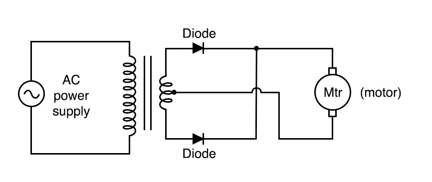
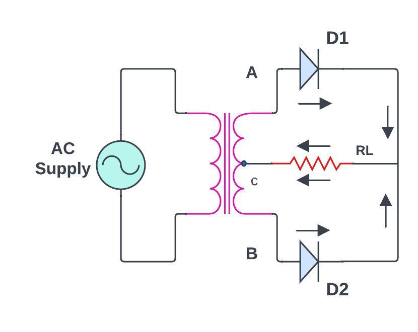
- Center tapped transformer diagram
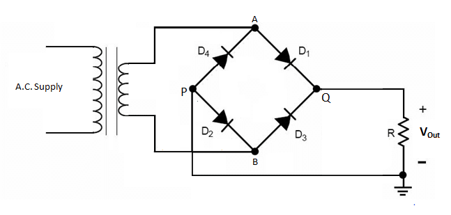
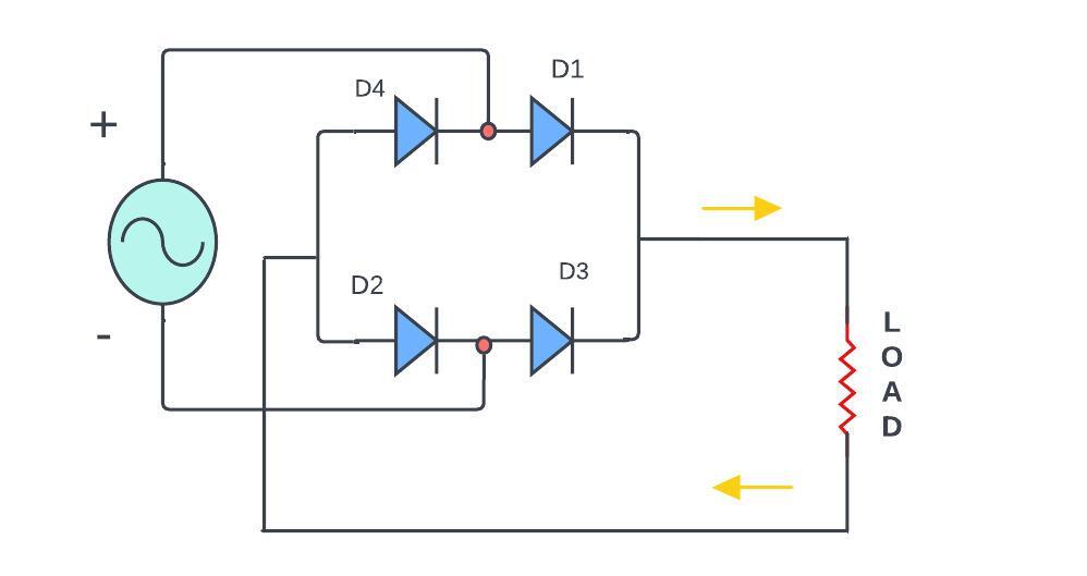
- Bridge rectifier Diagram
Does the full-wave bridge rectifier effectively convert AC to DC in different applications?
Both full wave and half wave rectifier converts alternative current (AC) to direct current (DC). However, the full wave rectifier, especially the full wave bridge rectifier, is more efficient compared to half wave rectifier.
Full wave rectifier gives smooth DC output with less ripple. It also offers high efficiency by using a four-diode configuration, whereas the half-wave rectifier uses only two diodes, that’s leading to a less efficient utilization of the input AC signal.
Is the full wave bridge rectifier better for efficiency?
If efficiency and a smooth DC output are required then the full wave bridge rectifier is the best options due to its enhanced performance compared to the half wave rectifier.
What is full wave bridge rectifier in short
a full wave bridge rectifier is an electrical circuit that is converts alternative current to direct current efficiently by using a specific arrangement of diodes.
What is the principle of full wave rectifier?
So let checkout the working principle of full wave rectifier here we go through the bridge rectifier in short and simple language as which is widely used
Components:
Four diodes (D1, D2, D3, D4)
Ac input source
Load resistor (RL)
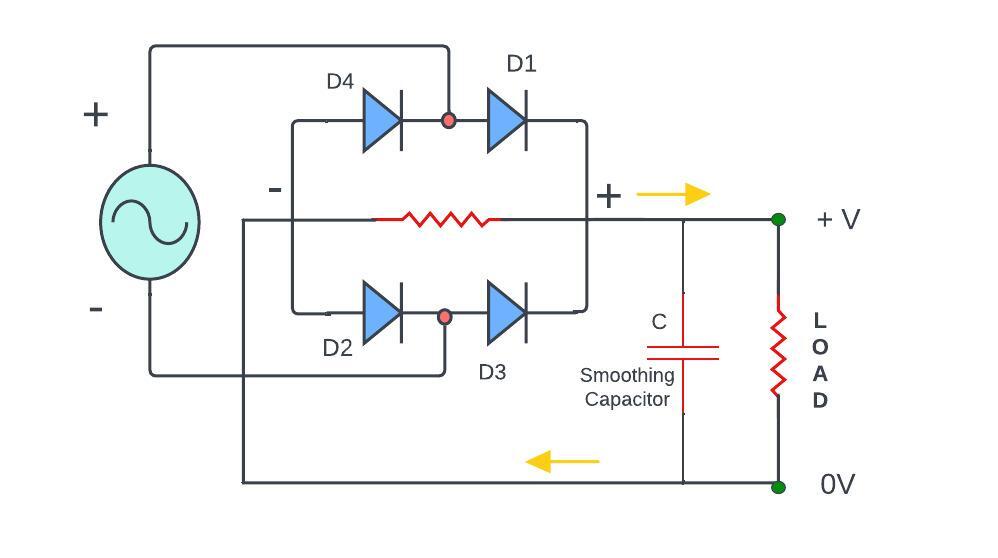
Capacitor (optional for smoothing)
Configuration:
The diodes are arranged in a specific pattern forming a bridge configuration and The AC input is connected to the two diagonally opposite ends of the bridge
Operation
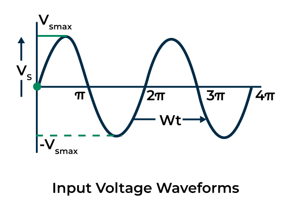
For positive half -cycle of the AC input:
The diode D1 and D2 becomes in Forward-biased that allowing current to flow through D1 to the load RL and through D2 to the Ac source.
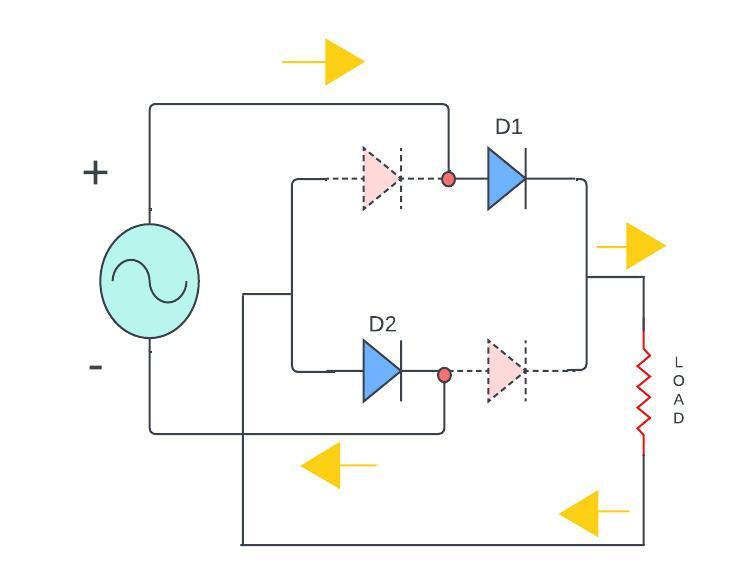
At a same time, Diode D3 and D4 are in reverse bias and these are not conducting
Reverse Half Cycle:
For negative half-cycle of the AC input:
Diodes D3 and D4 becomes Forward biased and that allows current to flow through D4 to the load Resistor RL and through D3 to the AC source.

Simultaneously, diode D1 and D2 are in reverse-biased and those are not conduct.
Output:
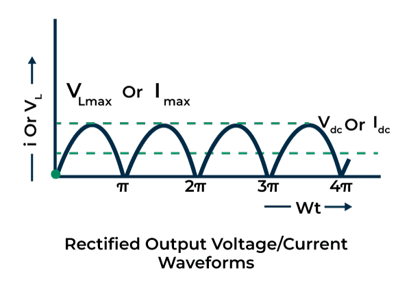
this arrangement allows current to flow through the load RL in the same direction during both half -cycle of the AC input.
As a result, the output across the load RL is a pulsating DC waveform with less ripple compared to a half-wave rectifier.
Optional Smoothing:

If we add a capacitor across the load RL so it helps in smoothing the pulsating DC output by storing charges during peak voltage and discharging during low voltage periods.
What are the Types of full wave rectifier?
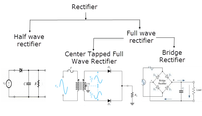
As the image suggest there are two primary types of rectifiers which are
- Half wave rectifier
- Full wave rectifier
But the Full wave rectifier divided into two more types –
- Center tapped
- Bridge rectifier
There are primarily two types of full wave rectifiers which are as follows:
Let’s discus one by one by-
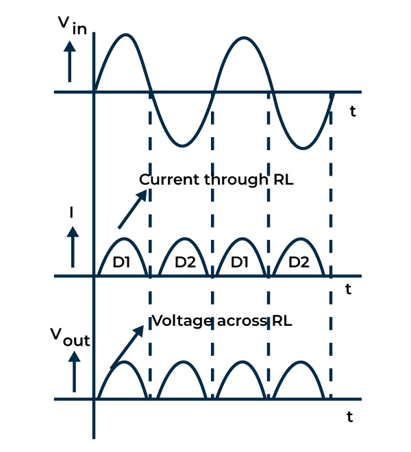
Centre-tapped full wave rectifier
This types of transformers with a centre-tapped secondary winding.
Two diodes are connected in a way that during the positive half cycle, one diode conducts and during the negative half-cycle other one diode is conduct so that utilizing both halves of the AC input cycle
Bridge rectifier
A bridge rectifier types utilizes four diodes arranged in a bridge configuration. So it does not required a center-tapped transformer that make it more common in used for various applications.
Input Image
Output Image
So Here is a brief information
| Aspect | Centre-tapped rectifier | Bridge rectifier |
|---|---|---|
| Transformer required | Required a center tapped transformer | Dose not required a center tapped transformer |
| Diode configuration | Uses tow diodes | Uses four diodes in a bridge configuration |
| Output voltage | Produces two separate pulsating DC voltages | Provides a continuous DC output during each AC cycle |
| Efficiency | Lower efficiency due to utilizing half of the winding | Higher efficiency by utilizing the entire winding |
| complexity | Generally simpler due to fewer diodes | Slightly more complex due to the arrangements of diodes |
| Advantages | Effective applying of both half parts of the input voltage | It gives higher efficiency because here is no need of center tapped transformer |
| Practical usage | Power supplies Battery charger Audio amplifier Low power devices | Household devices Electronic manufacturing Industrial equipment Automotive systems |
What is the ripple factor of a full wave rectifier?
The ripple factor of a full-wave rectifier is a measure of the amount AC components or ripples presents in the output DC signal.
It’s determined by the ratio of the root mean square (RMS) value of the AC components to the DC components in the output.
Typically, in a more consistent and smoother DC output compared to some other rectifiers.
What are the uses of full wave bridge rectifier?
After checkout the working principle of full wave bridge rectifier let’s look the uses-
Power supplies
Uses of full wave bridge rectifier are widely used in power supply circuits across electronic devices that’s provides a steady DC a output from an AC source or signal.
Household Applications
Applications of full wave bridge rectifier are found in numerous household applications like TV’s, Refrigerators and washing machines so it has ensured a stable DC power source for their operations.
Electronic Manufacturing –
Employed in manufacturing processes where consistent DC power is essential for testing and running electronic components and devices.
Battery Charger –
It utilized in charging circuits for batteries due to their ability to convert AC voltage to constant DC output.
Audio System –
Use of full wave bridge rectifier in Audio System For processing and amplification.
LED light –
Used in LED drivers and lighting systems to provide suitable voltage to drivers and led’s for their efficient working and less overheating and reduces damages.
Telecommunication –
For ensuring consistent power in telecom equipment’s
Renewable energy systems –
They found in renewable energy systems like wind turbines and solar plants to the generate AC power into usable DC power for storage or use in electrical grids.
Computer and IT equipment’s –
It employed in computer power supplies and IT equipment to ensure a stable and regulated DC voltage for their operations.
Medical devices –
Used in various medical devices and equipment where a consistent and reliable DC power source is required for better functionalities.
Filter Circuit using Full Wave Rectifier
Full Wave Rectifier Formula
Center-Tapped Full-Wave Rectifier Formula
To find the output DC voltage (Vout) of a center tapped full wave rectifier you can use the following equations:

Where,
Vout: Output DC voltage
Vm: Peak value of the AC voltage
ω: AC voltage frequency (2π times the frequency) t: Represents time within the cycle.
Bridge Rectifier Formula
In a bridge rectifier four diodes are employed to convert AC to DC those the output voltage (Vout) of this rectifier can as following formula
Vout = Vm – Vd
Vout: is the output DC voltage
Vm: peak value of the AC voltage
Vd: voltage drop across the diode (Around 0.7 volts for silicon diode)
Peak Inverse Voltage
The PIV, which stands for peak inverse voltage it represents the maximum reverse voltage that a diode within a full-wave rectifier needs to endure. This value is equal to the higher point of the incoming AC voltage.
PIV = Vm
Where,
Vm is the peak value of AC input voltage
DC output Voltage
The DC output voltage produces by a full-wave rectifier is roughly the peak value of the AC input voltage and that is reduced by the voltage drop across the diodes.
Vdc ≈ Vm – 2Vd
Where,
Vd is the voltage drop across each diode
RMS value of Current
The room mean square (RMS) of the current at the output of a full-wave rectifier can be determined by replaying on the RMS value of the input current
Irms = Im / 2
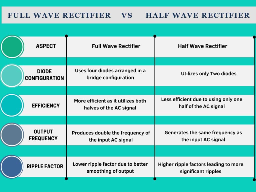
Difference between Full Wave Rectifier and Half Wave Rectifier
Efficiency of full wave rectifier?
the efficiency of a full wave rectifier is generally higher compared to a half wave rectifier. Because they have more continuous output. This means that the output voltage is produced for a lagger potation of time compared to a half wave rectifier and that’s lead to higher efficiency in converting AC to DC.
The maximum efficiency of a full wave rectifier is around 81.2% while a half wave rectifier typically achieved an around 40-60% efficiency.
FAQ’s
Q. Which rectifier is used most?
Ans: The full wave rectifier particularly the bridge rectifier is a commonly used due to its higher efficiency and better performance compared to half wave rectifier.
Q. How many diodes are there in full wave bridge rectifier?
Ans: There are four diodes used in F.W.B.R. circuit.
Q. What is the bridge configuration?
Ans: The diode are set up like a squad or Dimond shape like two diodes make a pair and there are two pairs are total.
Q. What’s the outcome?
Ans: It creates a path for the current to flow in the same direction through the load (like your electronic devices)
Q. Can a full wave bridge rectifier handle different input voltages?
Ans: Addressing its adaptability to varying input AC voltages and frequency.
Also Read
Zener Diode – Working, Characteristics and applications
VI Characteristics Of Pn Junction Diode- Comprehensive Study
How Freewheeling Diode Work: Easy Explanation
What is P-N junction Theory of semiconductor
Conclusion:
A full wave bridge rectifier efficiently converts AC to DC using four diodes arranged in a bridge configuration that enabling better utilizing of the input power for a smoother DC output.
