Mastering Kirchhoff’s Voltage and Current Laws _A Step-by-Step Guide
This blog post aims to provide a comprehensive introduction to Kirchhoff’s laws (KVL) and (KCL) for individuals who are new to the field of networking. It is designed to equip beginners with the foundational knowledge and practical skills needed to understand and apply these techniques.
KVL, often referred to as the loop rule, states that in any closed loop within a network or circuit, the algebraic sum of the voltages is zero.
Understanding voltage distribution and recognizing voltage dips between components are made possible by this law, which demonstrates the conservation of energy.
Kirchhoff’s Current Law Definition:
KCL, known as the node rule, asserts that at any junction or node within a circuit, the sum of currents entering the node must equal the sum of currents leaving it,
Kirchhoff’s Current Law (KCL):
- KCL is also known as the law of conservation of charge.
- The sum of the currents flowing into and out of any junction (or node) in an electrical circuit is equal to one another.
- This law is based on the principle that electric charge is conserved. In other words, the total charge entering a junction must equal the total charge leaving it.
- KCL is often used when analyzing circuits with multiple branches or when current divides at a junction.
- KCL can be represented as:
- ΣI in = ΣI out
- Here, ΣI_in represents the sum of currents entering the node, and ΣI_out represents the sum of currents leaving the node. The sum is taken algebraically, considering directions and signs.
Kirchhoff’s Voltage Law (KVL):
- KVL is based on the energy of conservation.
- It states that the sum of the electromotive forces (EMFs or voltage sources) and voltage drops in a closed loop of an electrical circuit is zero.
- This law is essential for analyzing loops or closed paths within a circuit, such as in loops containing resistors, capacitors, and inductors.
- KVL can be represented as:
- ΣV loop = 0
- Here, the ΣV loop represents the sum of all voltages encountered while traversing a closed loop in the circuit. The sum is taken algebraically, considering polarities and signs.
kvl and kcl formula:
Certainly, here are the formulas for Kirchhoff’s laws:
1. Kirchhoff’s Current Law (KCL):
· ΣI_in = ΣI_out
2. Kirchhoff’s Voltage Law (KVL):
· ΣV loop = 0
what is kcl and kcl with example:
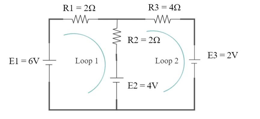
Q] Find the current in each branch.
Complete Step-by-Step Answer:
In this question, we need to find the current in each of the branches. so We have already been given two loops in the question with their direction, so we will move according to them
In 1st loop, using Kvl we get
2I1 + 2(I1 – I2) = 4 – 6
4I1 – 2I2 = -2…………(1)
In loop 2, using kvl we get
4I2 + 2(I2 – I1) = – 2 – 4
6I2 – 2I1 = -6…………(2)
By solving equation (1) and (2), we get
I1 = −1.2A
I2 = −1.4A
Here the negative sign indicates that the direction that we have chosen as positive is wrong and current moves in the opposite direction as what we have selected
Hence, Instead of an anti-clockwise direction the current moves in a clockwise direction.
the correct answer is;
I1 =1.2A
I2 =1.4A
kvl and kcl difference:
| Aspect | KCL (Kirchhoff’s Current Law) | KVL (Kirchhoff’s Voltage Law) |
| Focus | Current (Flow of Electric Charge) | Voltage (Potential Difference) |
| Conservation Principle | Conservation of Charge | Conservation of Energy |
| Mathematical Expression | ΣI in = ΣI_out | ΣV loop = 0 |
| Application | Nodes or Junctions in a Circuit | Closed Loops or Paths in a Circuit |
Important Conclusion:
Kvl and kcl are independent of the nature of the element.
For the validity of the circuit
- Kvl must be satisfied.
- Kcl must be satisfied.
- Energy conservation must be satisfied.
- Charge conservation must be satisfied.
– Analysing and solving complex electrical circuits.
– Designing electronic circuits, such as amplifiers, filters, and power supplies.
– Troubleshooting and diagnosing circuit problems.
– Ensuring that the principles of charge conservation and energy conservation are maintained in electrical systems.
Overall, Kirchhoff’s laws are fundamental tools for electrical engineers and physicists when working with electrical circuits and systems. They provide a systematic and rigorous way to analyse and understand how currents and voltages behave in various circuit configurations.
The Best comprehensive books for electronic which create solid foundations in circuit analysis
- “Fundamentals of Electric Circuits” by Charles Alexander and Matthew Sadiku
- “Electric Circuits and Networks” by K. S. Suresh Kumar
Frequently Asked Questions
- Is KVL applicable for series circuits?
Yes, Kirchhoff’s Voltage Law (KVL) applies to series circuits. KVL applies to any closed loop within an electrical circuit, including series circuits.
In a series circuit, components (such as resistors, capacitors, or inductors) are connected in a single path, one after the other, so there’s only one path for the current to flow. KVL can be applied to the entire series loop to analyze the voltage distribution across the components.
2. Is KVL valid for series or parallel?
Ans: KVL (Kirchhoff’s Voltage Law) is valid for both series and parallel circuits. It can be applied to any closed loop within an electrical circuit, regardless of whether the components are connected in series or parallel.
3. What are the limitations of KVL?
Ans: Kirchhoff’s Voltage Law (KVL) is a fundamental principle in electrical circuit analysis, but it has certain limitations and assumptions:
Linear Circuits
Steady-State Conditions
Low-Frequency AC Circuits
Single-Loop Assumption
Non-Ideal Components
Follow to the blog etechspark.com for more articles on electrical engineering and circuit analysis.
please leave your question in the comment section, give us your valuable feedback.