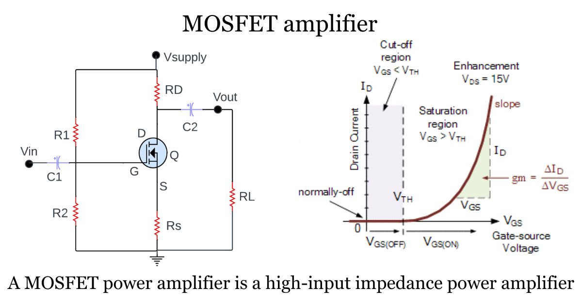
Definition of MOSFET amplifiers
MOSFET (Metal-Oxide-Semiconductor Field-Effect Transistor) power amplifier is a high input impedance power amplifier. They offer voltage amplification, and low power consumption. The configuration of MOSFET amplifier are Common configurations include common source, common drain, and common gate amplifiers. That will be discussed in this article.
As we seen in previous tutorials class A, class B and class C amplifier but the MOSFET amplifier provides more Linearity than others. This article focuses on the MOSFET amplifiers and tells you everything you need to know about it.
What is a MOSFET amplifier?
A MOSFET amplifier is an electronic circuit that uses MOSFET transistors as the active components to amplify electrical signals.
It operates by controlling the flow of current between the source and drain terminals of the MOSFET. MOSFET amplifiers are known for their high input impedance, low output impedance, and the ability to provide voltage amplification with low power consumption.
Operation of MOSFET Amplifiers
A Metal-oxide-semiconductor field-effect transistors (MOSFETs) are voltage-controlled devices that regulate the flow of current between the source and drain terminals based on the gate-to-source voltage. MOSFETs can operate in three modes: enhancement, depletion, and linear.

In enhancement mode, a positive voltage applied to the gate relative to the source creates a conductive channel between the source and drain, allowing current to flow. Conversely, in depletion mode, a conductive channel exists even without a gate voltage. The width of this channel can be modulated by adjusting the gate-to-source voltage.
When operating in linear mode, the MOSFET behaves like a resistor, with the drain current directly proportional to the gate-to-source voltage. This property makes MOSFETs valuable components in various electronic circuits, including amplifiers, switches, and voltage regulators.
Types of MOSFETs used in amplifiers
MOSFETs are commonly used in amplifiers, and they come in two primary types: N-channel and P-channel. These two types have complementary characteristics and can be used in various amplifier configurations. Here is a brief overview of each type:
What is N-channel MOSFETs?
It is an essential semiconductor device in electronics. These have three key terminals: source, gate, and drain. the Gate Control Applying a positive voltage to the gate (relative to the source) allows the flow of electrons from the source to the drain.
There are two Operating Modes in N type Mosfet amplifier
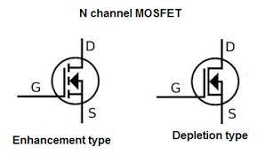
Enhancement Mode: Off until voltage is applied to the gate.
Depletion Mode: On by default, it needs a negative voltage to turn off.
Efficiency and Uses of an n-type Mosfet amplifier
The N-channel MOSFETs are Popular for their low on-state resistance. These are ideal for efficiently switching applications. This type is commonly used in power amplifiers, power supplies, motor control, and digital logic circuits. An N-channel MOSFETs are versatile and crucial in modern electronics for switching and amplification tasks.
What is P-channel MOSFETs?
P-Channel MOSFET (PMOS) works by controlling the flow of current between its source and drain terminals based on the voltage applied to its gate terminal. When a low voltage is applied to the gate, the PMOS conducts current. When a high voltage is applied to the gate, it switches off the current flow. This behavior makes PMOS transistors function as electronic switches or amplifiers, allowing precise control over electrical signals in electronic circuits.
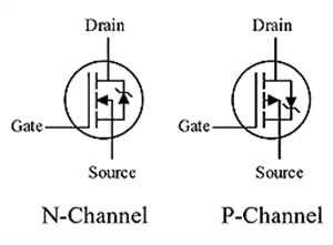
P-channel MOSFETs are typically used in common-source amplifier configurations. They provide low input impedance and are commonly used in low-frequency and high-input impedance applications.
In amplifier circuits, N-channel, and P-channel MOSFETs can be used together in a complementary push-pull configuration to improve efficiency and reduce distortion. Complementary push-pull amplifiers are often used in audio power amplifiers and other applications where high power and low distortion are important.
Types of MOSFET Amplifiers
There are three Types of MOSFET Amplifiers namely
That we will discuss brief manner in below one by one
The Common Source MOSFET Amplifier
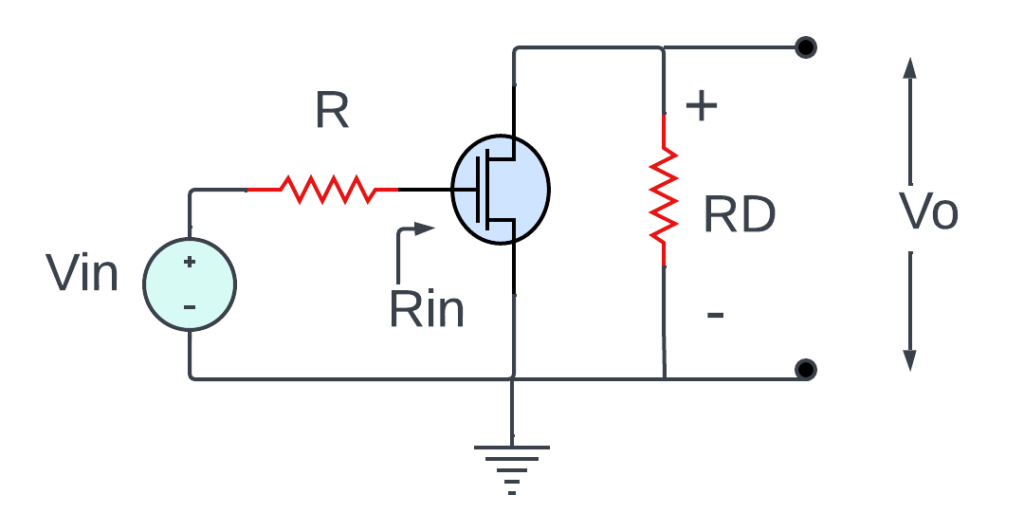
Operating Principles of Common Source MOSFET Amplifiers:
firstly, A small input voltage (AC signal) is applied to the gate of the MOSFET transistor.
Then the biasing network sets a suitable DC voltage at the gate terminal to establish the quiescent operating point.
The AC signal at the gate causes the MOSFET to conduct varying currents between the drain and source terminals.
The varying drain current results in a voltage drop across the load resistor, which amplifies the output signal at the drain terminal.
The source resistor provides negative feedback, improving stability and linearity.
Provide circuit diagrams for each configuration.
The Common-Gate (CG) Amplifier

the Operating Principles of a Common-Gate (CG) Amplifier:
When an Ac input signal is applied to the gate terminal of the MOSFET, it modulates the voltage at the gate.
Then the biasing network sets an appropriate DC voltage at the gate terminal to establish the quiescent operating point.
As the input changes, it affects to voltage at the gate, which in turn influences the current flow between the drain and source terminals.
Then this varying drain current results in a voltage drop across the load resistor, generating an amplified output signal at the drain terminal.
Finally, the source resistor provides negative feedback, which can help improve the linearity and stability of the amplifier.
The Common Drain Amplifier
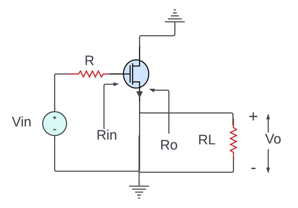
Operating Principles of the Common Drain Amplifier
When an AC input signal is applied to the gate terminal of the MOSFET, it modulates the voltage at the gate.
Then the biasing network sets an appropriate DC voltage at the gate terminal to establish the quiescent operating point.
As the input signal is changing, it will affects to the voltage at the gate terminal, which cause to the current flowing between the drain and source terminals.
This varying drain current results in a voltage drop across the load resistor, generating an amplified output signal at the source terminal.
MOSFET Amplifier Solved Problems
Problem 1: Common Source Amplifier
MOSFET transconductance (gm): 2 mS (milliSiemens)
Drain resistor (RD): 5 kΩ (kilo-ohms)
Source resistor (RS): 1 kΩ
Drain supply voltage (VDD): 10 V
Input signal voltage (Vin): 100 mV (millivolts)
Calculate the following:
a. Quiescent (DC) drain current (IDQ).
b. Drain-source voltage (VDS) at the quiescent point.
c. Voltage gain (Av) of the amplifier.
d. Output voltage swing (peak-to-peak) for maximum undistorted output.
Solution:
a. Quiescent (DC) Drain Current (IDQ):

VGS (Gate-Source Voltage) is typically around 2 to 3 V for an N-channel MOSFET in the saturation region, but it’s best determined from a datasheet. Let’s assume VGS = 2.5 V.
IDQ = (10 V – 2.5 V) / 5 kΩ = 1.5 mA
b. Drain-Source Voltage (VDS) at the Quiescent Point:

VDS = 10 V – (1.5 mA * 5 kΩ) = 2.5 V
c. Voltage Gain (Av):

“||” represents the parallel combination.
Av = -2 mS * (5 kΩ || 1 kΩ)
Av ≈ -2 mS * 833.33 Ω ≈ -1.67
d. Output Voltage Swing (peak-to-peak) for Maximum Undistorted Output:
To avoid distortion, you typically design for VDS to remain greater than a certain value (often a few volts). Let’s assume we want VDS to be at least 3 V for maximum output. This means VDS can swing between 2.5 V (quiescent) and 5.5 V (maximum).
Problem 2: Common Drain (Source Follower) Amplifier
Consider a Common Drain (Source Follower) Amplifier circuit with the following parameters:
MOSFET transconductance (gm): 1.5 mS
Source resistor (RS): 1.2 kΩ
Drain supply voltage (VDD): 12 V
Input signal voltage (Vin): 200 mV
Calculate the following:
a. Quiescent (DC) source current (ISQ).
b. Source voltage (VS) at the quiescent point.
c. Voltage gain (Av) of the source follower.
d. Output voltage swing (peak-to-peak) for maximum undistorted output.
Solution:
a. Quiescent (DC) Source Current (ISQ):
ISQ = (VDD – 2 * VGS) / (2 * RS)
Assuming VGS = 3 V (check the datasheet for the specific MOSFET).
ISQ = (12 V – 2 * 3 V) / (2 * 1.2 kΩ) = 3 mA
b. Source Voltage (VS) at the Quiescent Point:
VS = VGS (Gate-Source Voltage) = 3 V
c. Voltage Gain (Av):
Av ≈ 1
The Common Drain amplifier (Source Follower) provides nearly unity voltage gain.
d. Output Voltage Swing (peak-to-peak) for Maximum Undistorted Output:
Since the source follower has a voltage gain close to 1, it can closely follow the input voltage. The output voltage swing is primarily determined by VDD. Assuming VDD remains constant, the output voltage can swing from (VDD – VGS) to (VDD – VGS).
These problems illustrate how to calculate important parameters and characteristics of MOSFET amplifiers, whether in the Common Source configuration or the Common Drain (Source Follower) configuration.
Difference between BJT and MOSFET Amplifier
| Feature | BJT Amplifier | MOSFET Amplifier |
|---|---|---|
| Type of control | Current | Voltage |
| Input impedance | Low | High |
| Output current | High | Moderate |
| Switching speed | Slow | Fast |
| Power consumption | High | Low |
| Applications | Audio amplifiers, low-power circuits | RF amplifiers, digital circuits |
Characterises of Mosfet amplifier
these amplifiers are extensively employed in electronic circuits owing to their beneficial traits. Here is a concise overview of the crucial characteristics of MOSFET amplifiers:
- Superior Input Impedance: MOSFETs draw a minimal current from the input signal source, ensuring minimal loading effects on the input signal.
- Reduced Output Impedance: MOSFETs efficiently drive the load connected to their output terminals, facilitating efficient power transfer from the amplifier to the load.
- Voltage-Responsive Operation: MOSFETs are voltage-controlled devices, meaning their output current is directly proportional to the input voltage, making them suitable for voltage amplification applications.
- Versatile Operating Range: MOSFETs can operate over a broad range of voltages and currents, rendering them flexible components for various electronic circuits.
- Swift Switching Capability: MOSFETs can switch between on and off states very rapidly, making them applicable for high-frequency applications.
- Efficient Power Consumption: MOSFETs generally consume less power compared to other transistor types, such as BJTs, contributing to energy-efficient circuit designs.
- High Linearity: MOSFETs exhibit exceptional linearity in their transfer characteristics, ensuring accurate reproduction of the input signal’s waveform.
- Pristine Noise Performance: MOSFETs are recognized for their low noise levels, making them suitable for applications where minimizing noise is critical.
- Compact Fabrication: MOSFETs can be scaled to very small dimensions, enabling the fabrication of miniature and integrated circuits.
- Reliable and Durable Performance: MOSFETs are highly reliable and robust devices, capable of withstanding demanding operating conditions and maintaining their performance over time.
key formulas Mosfet amplifiers
The o/p voltage (Vout)
Vout = – RD x ID = -gmVGS RD
Voltage Gain
Av = – RD/Rs=1/gm
Advantages of Mosfet amplifier
Advantages of Mosfet amplifier as following-
- The Mosfet amplifier has low losses.
- communication speed of this Mosfet amplifier is high.
- it occupies less space and fast.
- Consumes less power as compared to BJTs.
- FET amplifiers have very high i/p impedance & low o/p impedance.
- It is better as compared to other devices like Thyristor, IGBT, etc.
Disadvantages of Mosfet power amplifier
- They are widely used for automotive, industrial and communications systems.
- Power MOSFETs are commonly used in automotive electronics, particularly as switching devices in electronic control units.
- Also, as power converters in modern electric vehicles.
Frequency Asked Questions [FAQs]
Q. What is the conclusion of MOSFET amplifier?
Ans: A MOSFET (Metal-Oxide-Semiconductor Field-Effect Transistor) power amplifier is a high input impedance power amplifier.
Q. What is the uses of MOSFET amplifier?
Ans: the main purpose of using this device is for automotive, industrial and communications.
Q. Is MOSFET a switch or amplifier?
Ans: MOSFETs can be used as both switches and amplifiers.
As a switch: MOSFETs can be turned on and off very quickly, making them ideal for switching high currents and voltages. MOSFETs are often used in power electronics applications such as motor control, power supplies, and inverters.
As an amplifier: MOSFETs can amplify electrical signals in a linear fashion. This makes them useful for applications such as audio amplifiers, RF amplifiers, and sensor interfaces.
Q. Which MOSFETs are mostly used?
Ans: The most popular MOSFETs are IRFZ44N, 2N7002, and FQP30N06L. They are general-purpose, inexpensive, and easy to find.
Q. Is A MOSFET AC or DC?
Ans: However, MOSFETs can be used with AC signals by using a bridge rectifier to convert the AC signal to DC before it is applied to the MOSFET. This allows the MOSFET to be used as a switch to control the AC load.
MOSFETs are also used in AC power supplies to switch the input AC signal to produce a regulated DC output.
Q. What is better MOSFET or relay?
Ans: The best choice for a particular application depends on the specific requirements of that application. For example, if fast switching speed and high efficiency are important, then a MOSFET is the better choice. However, if electrical isolation or high voltage/current switching are required, then a relay is the better choice.
Also Read:
Summery:
In summary, A MOSFET amplifier is an electronic circuit that uses a metal-oxide-semiconductor field-effect transistor (MOSFET) to amplify an electrical signal. MOSFET amplifiers are commonly used in a wide variety of applications, such as audio amplifiers, RF amplifiers, and sensor interfaces. MOSFET amplifiers are versatile electronic circuits that can be used to amplify a wide variety of electrical signals. They offer a number of advantages over other types of amplifiers, such as high input impedance, high voltage gain, and low power consumption.
Follow to the blog ETechSpark.com for more articles on electrical engineering, electronic and tech updates. please leave your question in the comment section, give us your valuable feedback.
