In this blog post, we will talk all about centrifugal switches, what they are, how they are used and where and many more, so stay tuned as we explain the basis and importance of centrifugal switches in different industries and technologies. So, Let’s begin
What is a Centrifugal Switch in a Motor?
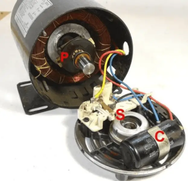
A centrifugal switch is an electrical device commonly used in single-phase and split-phase induction motors. It was patented by Royal Lee in the 1920s and has since transformed motor technology by providing controlled switching operations necessary for maintenance of specific motor speeds.
Why Centrifugal Switch Invented?
Before the invention of the centrifugal switch, motor designs often placed switches inside the motor frame.
However, this approach had several drawbacks dust, oil and grease would accumulate on these internal switches, leading to unhealable contact and causing problems with motor performance and maintenance.
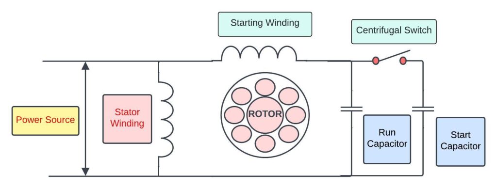
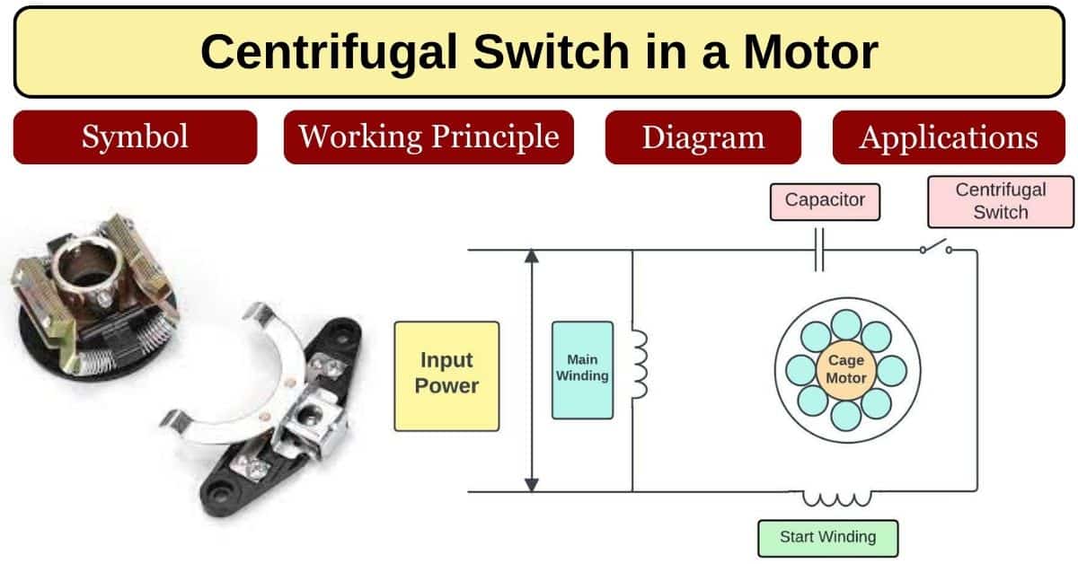
Centrifugal Switch Electrical Symbol

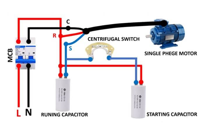
Centrifugal Switch Connections diagram
Need of Centrifugal Switches
If the centrifugal switches address the above issue by harnessing the centrifugal force generated by the rotating shaft, this force activated or deactivated the switch based on predetermined speed thresholds, while also ensuring smooth and reliable motor operation.
This innovation has significantly improved the performance and long life of induction motor these characterises making a crucial advantage in motor technology.
So, here basically one question come in mind that is-
What is Centrifugal Force?
Centrifugal force is the outward force experienced by an object in a curved path due to its inertia. It has a perceived effect on rotation systems.
How Does a Centrifugal Switch Work?
A centrifugal switch responds to the spinning of a motor’s shaft. As the shaft rotates then centrifugal force causes the switch to open or close to control the flow of the electrical current.

It typically activates or deactivates certain components to circuits within the motor based on its speed to ensure efficient operation and protection against damage.
Working Principles of Centrifugal Switch?
A centrifugal switch placed on a motor’s shaft, uses spinning force to trigger contact. It starts the motor by powering the starting windings and stop once te motor is running. So, it can save energy and ensure safety.
What Are the Characteristics of Centrifugal Switch?
Here are the technical specifications that are commonly associated with centrifugal switches
- Rated voltage:
specifies the voltage at which the centrifugal switch is designed to operate safely and effectively, such s 120V or 240V AC. - Rated current:
indicates the, maximum current that the switch can handle without malfunctioning or overheating, usually given in amperes (A). - Switching speed:
defines the rotational speed at which the switch activates or deactivates most typically there measured in revolution per minute (RPM) or as a percentage of the motor’s maximum RPM. - Temperature Range:
a temperature range specifies the operating temperature range within which the switch can function reliable that ensure proper performance in different environmental conditions. - Contact configuration:
it describes the type of electrical contacts used in the switch such as normally open (NO) and normally closed (NC) or changeover contacts. - Insulation class:
a insulation class indicates the insulation rating of the switch, which determines its ability to withstand electrical stress and prevent it from short circuits or breakdowns. - Mechanical durability:
it specifies the number of cycles or hours of operation that the switch can withstand before requiring maintenance or replacement.
What Are the Consequences If the Centrifugal Switch Fails to Open?
If the centrifugal switch doesn’t open correctly in a motor, it means the starting winding or circuit will remain active even after the motor reaches its desired speed.
This can lead to overheating of the starting components sometimes can be burn also reduce efficiency, potential motor stalling during operation, increased wear on the motor’s parts and ultimately reduces the lifespan of the motor if the issue isn’t addressed promptly.
What Is Centrifugal Switch in Induction Motors
In an induction motor, a centrifugal switch plays a key role during the startup phase.
When the motor is turned on then both the main winding and the starting winding receive electric power. The starting winding generates a rotating magnetic field that initiates the motor’s rotation.
When the centrifugal switch is typically mounted on the motor shaft it becomes activated as the motor speeds up and it usually has weighted arms or springs attached.
At lower speed or when the motor is stationary, then the weighted arms or springs maintain the connections to starting windings. it is important to provide the initial torque needed to start the motor smoothly.
As the motor accelerates then the centrifugal forces act on the weighted arms or springs causing them to move outward. Once the motor reaches a specific speed (known as the switch-off speed) then the centrifugal force surpasses the spring and the switch contacts open.
When the switch contacts open, the starting windings disconnect from the circuit. After the switch opens, the motor continues running using only the main windings. The starting windings remains disconnected until the motor is turned off and restarted
How To Test a Centrifugal Switch?
To test a centrifugal switch in an induction motor, begin by disconnecting the motor from power to ensure safety.
So, for simplicity we will discuss it step by step-
- Safety first: make sure the motor is unplugged to stay safe.
- Find the switch: look for the centrifugal switch inside the motor housing and near the shaft end.
- Visual check: inspect the switch for damage such as burned parts or loose connections.
- Resistance test: use a multimeter set to measure resistance (ohms). If needed, disconnect the switch from the motor circuit.
- Check continuity: put multimeter probes on the switch terminals. when the motor is still (not running), the switch should be closed, which is showing low resistance. This means it’s making good contact at rest.
- Test opening: turnthe motor shaft manually or with a tool. As the shaft spins faster than the switch should open that showing a high resistance. This mimics how the switch opens at a higher speed during normal motor use.
- Confirm operation: now watch the multimeter as spin the shaft. The resistance should go from low (closed) to high (open) as the speed increases that shows the switch works correctly.
- Connect and test the motor: if the switch passes the resistance test, then connect it back to the motor circuit and test the motor. Make sure it starts and runs smoothly without odd sounds or vibrations.
- Final check: after testing, put everything back together and check all connections. Then plug the motor back in and make sure everything is secure.
Following these steps helps you test a centrifugal switch in an induction motor to ensure it’s working right.
When We Don’t Need Centrifugal Switch
a centrifugal switch is not required for certain motor types or applications where alternative starting methods are used. These includes capacitor-start motors, permanent split capacitors (PSC) motors, dual-voltage motors with different winding configurations and high-efficiency motors with advanced control systems.
Additional specialized applications may use soft starters or variable frequency drivers (VFD) instead of a centrifugal switch for motor starting.
What Are the Advantages of Centrifugal Switches?
- Centrifugal switches in induction motors:
- Save energy by stopping the starting windings at the correct speed.
- Protect the motor from damage by avoiding using the starting windings for too long
- Improve how well the motor works and how reliable it is
- are cost-effective ways to current the motor.
Applications of Centrifugal Switches
Centrifugal switches have several applications in various mechanical and electrical systems. Some common applications include-
- Electric motors: used in single-phase induction motors for starting and running operations to improve efficiency.
- Pumps: for controlling motor and stopping in centrifugal pumps for operation.
- Compressors: to manage motor operation in compressors systems to maintain performance.
- Fans: control motor speed in fan systems like HVAC units for energy efficiency.
- Power tools: incorporated in certain power tools to manage motor functions based on usage requirements.
Centrifugal Switch Applications in Induction Motor
Start capacitor control-
Centrifugal switches start in one phase induction motors by connecting the starting capacitors initially and then disconnecting it once the motor reaches a certain speed.
Start winding control-
These control the starting windings in induction motors that ensuring it’s active during startup and then deactivating it as the motor accelerates.
Motor protection-
These switches can protect motors by tripping or opening the circuit in case of overload or overheating so it can prevent from damages.
Speed sensing-
Some switches act as speed sensors that trigger control functions or indicators based on specific motor speeds in induction motors.
Frequently Asked Questions (FAQ’s)
Q. Is A Centrifugal Switch Normally Open or Closed?
Ans: a centrifugal switch is normally closed during the starting phase of an induction motor.
Q. Do All Single-Phase Motors Have a Centrifugal Switch?
Ans: not all single-phase motors have a centrifugal switch. They are typically found in motors used for pumps, fans, and compressors to disconnect the starting winding once the motor reaches its operating speed.
Q. Can Motor Run Without Centrifugal Switch in Induction Motor
Ans: Yes, an induction motor can run without this switch. However, the absence of a centrifugal switches may affect certain functionalities such as efficient starting, control of starting components like capacitors or windings.
Q. What is the alternative to centrifugal switch?
Ans: A Triac-based control system is an electronic alternative to a centrifugal switch in some induction motors.
Q. What is Auxiliary winding?
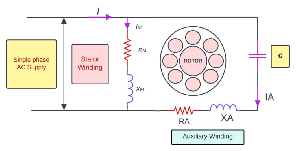
Ans: an auxiliary winding is an additional coil of wire in an electric motor that typically found in single-phase induction motors. It is used to create a rotating magnetic field necessary for starting the motor and providing initial torque.
Conclusion
A centrifugal switch in a motor is a crucial component that helps in starting and stopping the motor effectively. It operates based on centrifugal force, which is generated when the motor reaches a certain speed.
This force causes the switch contacts to open or close and enabling the motor to start or stop as needed.
Recent posts
Single-phase AC Motor Speed Control – How it works?
All about Motor Starter – Working principle, Types, features, application
Very informative content